Warning
I did everything kinda raw in this tutorial, which means it’s probably faster if you didn’t read this and instead looked for a library to do it for you. Also, I just learned this yesterday, so take my word with a grain of salt and a corn of pepper.
The DHT11 Sensor
I’m sure many people familiar with Arduinos and microcontrollers and such know about this little guy. I actually just found out about this the other day. It basically just tells you about the current temperature and humidity, with a range of 0-50C and 20-90% relative humidity respectively. The accuracy is stated to be within 2C and 5% RH, which is enough for our purposes (fooling around).
Wiring
I’ve never actually done this before, so I’m reading the handy datasheet. If you want to follow along here is the one I’m using.
All you really need to do is connect positive to the 3.3v pin and negative to ground. The signal pin connects to a GPIO pin, more on that later.
Tip
Normally you’d have to use a 5k pull up resistor for the signal, unless yours comes in a module like the one I got from a Temu electronics kit, in which case it’s already in there so there’s no need to worry about it.
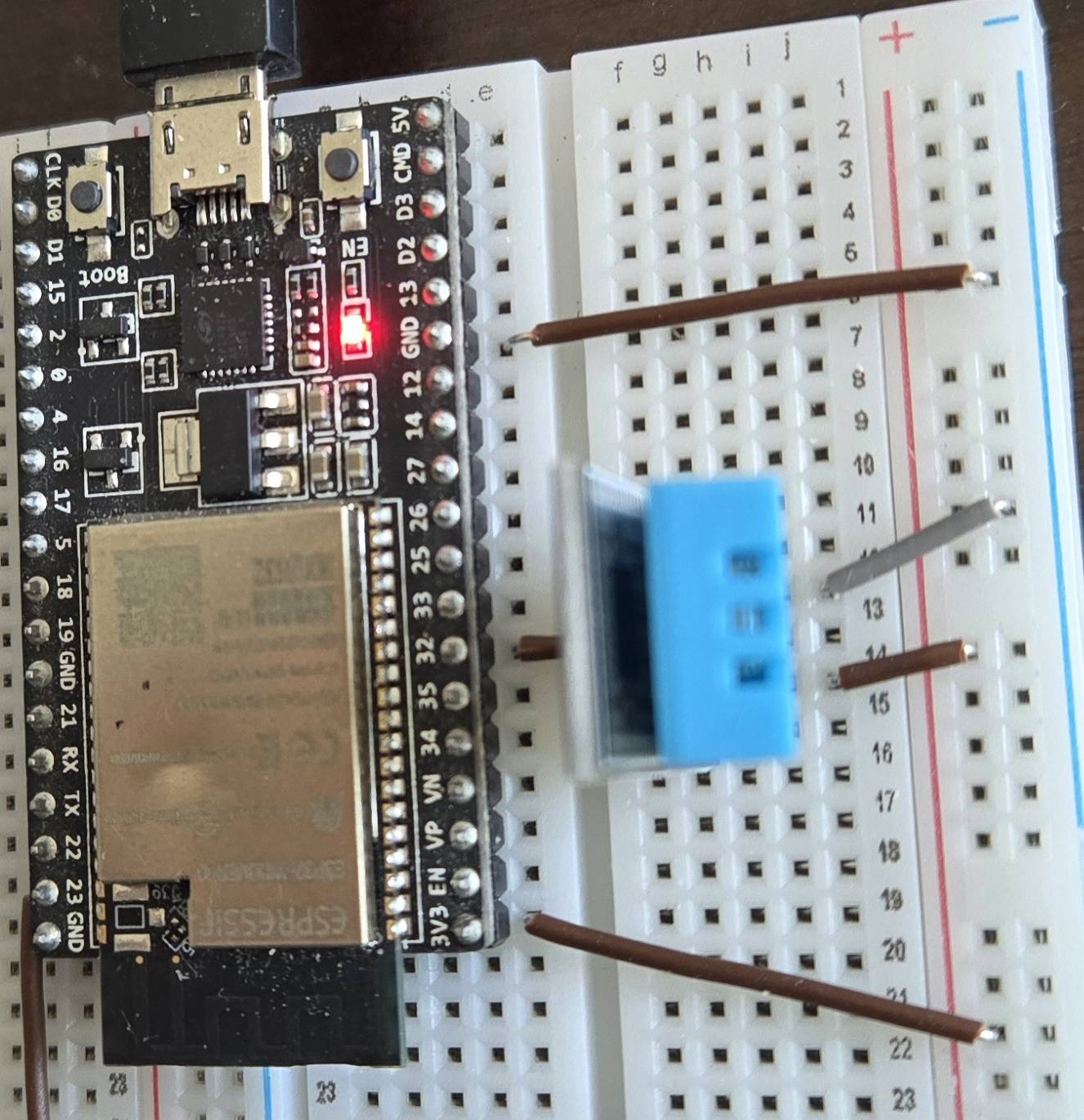
Here is a neat little picture.
Specs
Great we got the wiring done. Now we have to actually make a program to get the data. Here’s a TDLR of the process stated by the datasheet. Note that the default state of the signal pin is high.
- MCU (our esp32) sends start signal by pulling line down for at least 18ms
- MCU pulls line back up for 20-40s (microseconds)
- DHT pulls line low for 80s
- DHT pulls line high for 80s
- DHT sends data
The Data
The data response consists of 40 bits of data, comprised of:
- 8 bit integral relative humidity data
- 8 bit decimal relative humidity data
- 8 bit integral time data
- 8 bit decimal time data
- 8 bit checksum
The checksum is the last 8 bits of the previous four added together.
The actual sending of bits is pretty simple. The line is first pulled low for 50s to signal data transmission, then pulled high for 26-28s for a 0, or 70s for 1, then it repeats 39 times for the rest of the data.
Programming
One’s first thought for reading the sensor is to simply send the required signals for the required amount of time, then wait for the 80s pulses, wait 50s, read the signal, wait another 50s, etc.
However, a trusted associate told me that doing it this way is condemning your microcontroller to busy waiting and makes it hard to extend with other components. Surely we can do better.
In fact, we can indeed do better, at the cost of a light drain on sanity. A small price to pay for efficiency!
The Remote Control Transceiver (RMT) Peripheral
Initially designed as an infrared transceiver, RMT is flexible enough to use as a general purpose transceiver for other types of signals, which includes the single-wire one we’re working with. It can be broken down into two parts, the transmitter and the receiver.
RMT Transmitter
Our goal with the transmitter is to send out the required pulses and timings to the DHT11 sensor to get it to respond with the 40 bit data. This all boils down to one function: rmt_transmit(), which requires a lot of setup to use but we’re using it anyways because the speed and precision of the RMT hardware peripheral is probably better for the long run.
Here’s the signature for our function:
esp_err_t rmt_transmit(rmt_channel_handle_t tx_channel, rmt_encoder_handle_t encoder, const void *payload, size_t payload_bytes, const rmt_transmit_config_t *config)
What a doozy huh? Let’s take a look at the parameters. From the official docs:
tx_channel: RMT TX channel created byrmt_new_tx_channel()encoder: RMT encoder created by various factory APIs likermt_new_bytes_encoder()payload: The raw data to be encoded into RMT symbolspayload_bytes: Size of thepayloadin bytesconfig: Transmission specific configuration
tx_channel
Our first parameter is the transmit channel handle, which we can create with the provided function, rmt_new_tx_channel(). This one is much simpler:
esp_err_t rmt_new_tx_channel(const rmt_tx_channel_config_t *config, rmt_channel_handle_t *ret_chan)
config: TX channel configurationsret_chan: Returned generic RMT channel handle
config
There’s a lot of options, but we don’t really need everything. Here is a minimum config:
const rmt_tx_channel_config_t tx_chan_config = {
    .gpio_num = DHT_IO,
    .clk_src = RMT_CLK_SRC_DEFAULT,
    .resolution_hz = 1000000,
    .mem_block_symbols = 64,
    .flags.invert_out = false,
    .flags.with_dma = false,
    .trans_queue_depth = 4,
};- .gpio_num: set this to whatever number GPIO you’re using. Usually can be set to any of the normal I/O pins
- .clk_src: I just use default here
- .resolution_hz: 1,000,000Hz is 1MHz, which has a 1s period.
- .mem_block_symbols: Should be at least 64 if DMA is not enabled.
- .flags.invert_out: inverting the signal would just confuse me
- .flags.with_dma: false because my MCU doesn’t support it. Try experimenting with it if its available
- .trans_queue_depth: number of transactions that can be prepared in the backlog. 4 seems reasonable.
More information can be found on the docs
ret_chan
This is simply a pointer to a channel handle that will be populated by the function. You can just do something like this:
rmt_channel_handle_t tx_handle = NULL;
ESP_ERROR_CHECK(rmt_new_tx_channel(&tx_chan_config, &tx_handle));
It’s probably good practice to wrap these in ESP_ERROR_CHECK, which terminates the program if the check fails and prints useful information to serial.
encoder
This part confused me a lot. TLDR, we need to use a copy encoder, which doesn’t do any conversion and simply sends our symbols as is. We can initialize one with rmt_new_copy_encoder().
esp_err_t rmt_new_copy_encoder(const rmt_copy_encoder_config_t *config, rmt_encoder_handle_t *ret_encoder)
config: Copy encoder configurationret_encoder: Returned encoder handle
config
Espressif must’ve thought the tx_channel config was too long, because this struct has has no members. Its literally just:
rmt_copy_encoder_config_t copy_encoder_config = {};Apparently they plan to add stuff to it later, but right now you just have to pass in a blank config.
ret_encoder
Like tx_channel, you just need a place for the function to put the handle.
rmt_encoder_handle_t dht_encoder = NULL;
ESP_ERROR_CHECK(rmt_new_copy_encoder(©_encoder_config, &dht_encoder));payload
If you remember the description of the payload parameter from earlier, you’ll notice it’s supposed to be raw data that’ll be encoded into RMT symbols. Since we’re using the copy encoder, the data won’t be changed at all, meaning we would just pass in the RMT symbols directly.
What exactly are RMT symbols you ask? Allow me to copy paste the docs:
union rmt_symbol_word_t
struct rmt_symbol_word_tuint16_t duration0uint16_t level0uint16_t duration1uint16_t level1
uint32_t val
The union of the struct and the 32 bit integer basically allows you to access data members either as individual struct members or as a single 32 bit integer. We’ll just be using the struct members.
The duration and levels are pretty self explanatory. Each symbol encodes two actions. Form the DHT11 datasheet, the start signal needs requires pulling the line low for at least 18ms then high for 20-40s. Here’s what our payload will look like:
rmt_symbol_word_t start_pulse = {
	.duration0 = 20000,
	.level0 = 0,
	.duration1 = 30,
	.level1 = 1,
};
Note
The duration is in ticks, which we’ve defined in the
resolution_hzmember oftx_chan_configfrom earlier.duration0is set to 20ms to be safe,duration1is 30s as a middle ground between 20 and 40
payload_bytes
This is just sizeof(payload). Easy
config
The transmit function also has its own config. Here’s what we’ll use:
rmt_transmit_config_t tx_config = {
	.loop_count = 0,
	.flags.eot_level = 1,
};
This is pretty much all you need. It’s setting the transmit function to run only once and to set the level of the pin to high after it’s done transmitting.
Current Code
We also have to add a slight delay at the beginning for the sensor to turn on. This can be done with the vTaskDelay function from FreeRTOS. I just added this line before transmitting:
vTaskDelay(pdMS_TO_TICKS(2000));Don’t forget to #include "freertos/FreeRTOS.h"
Didja know?
vTaskDelay is based on ticks, which could be different across implementations, so we use a tick-to-millisecond converter. The above function guarantees at least 20ms of wait, with a couple extra ms of overhead.
Lastly, all we have to do is enable the channel handle with:
ESP_ERROR_CHECK(rmt_enable(tx_handle));After all that, we can finally call the transmit function. Here’s what the code should look like so far:
#include "driver/rmt_tx.h"
#include "freertos/FreeRTOS.h"
#define DHT_IO GPIO_NUM_32
const rmt_tx_channel_config_t tx_chan_config = {
.gpio_num = DHT_IO,
.clk_src = RMT_CLK_SRC_DEFAULT,
.resolution_hz = 1000000,
.mem_block_symbols = 64,
.flags.invert_out = false,
.flags.with_dma = false,
.trans_queue_depth = 4,
};
rmt_copy_encoder_config_t copy_encoder_config = {};
const rmt_symbol_word_t start_pulse = {
.duration0 = 20000,
.level0 = 0,
.duration1 = 30,
.level1 = 1,
};
const rmt_transmit_config_t tx_config = {
.loop_count = 0,
.flags.eot_level = 1,
};
void app_main(void) {
// Create new tx channel handle
rmt_channel_handle_t tx_handle = NULL;
ESP_ERROR_CHECK(rmt_new_tx_channel(&tx_chan_config, &tx_handle));
// Create encoder
rmt_encoder_handle_t dht_encoder = NULL;
ESP_ERROR_CHECK(rmt_new_copy_encoder(©_encoder_config, &dht_encoder));
// Enable channel
ESP_ERROR_CHECK(rmt_enable(tx_handle));
// Delay 2ms for sensor to turn on
vTaskDelay(pdMS_TO_TICKS(2000));
// Finally, transmit
ESP_ERROR_CHECK(rmt_transmit(tx_handle, dht_encoder, &start_pulse, sizeof(start_pulse), &tx_config));
}
RMT Receiver
Getting the data is kind of the whole point of doing this. After signaling the DHT11 to send data, we have to immediately start listening so we don’t miss anything. The function we’re interested in is rmt_receive(), which requires setup similar to rmt_transmit(). Here’s the signature:
esp_err_t rmt_receive(rmt_channel_handle_t rx_channel, void *buffer size_t buffer_size, const rmt_receive_config_t *config)
rx_channel: RMT RX channel created byrmt_new_rx_channel()buffer: The buffer to store the received RMT symbolsbuffer_size: the size ofbuffer, in bytesconfig: Receive specific configurations
rx_channel
Like the transmit function, this takes a config and a handle
esp_err_t rmt_new_rx_channel(const rmt_rx_channel_config_t *config, rmt_channel_handle_t *ret_chan)
config: RX channel configurationsret_chan: Returned generic RMT channel handle
config
const rmt_rx_channel_config_t rx_chan_config = {
    .gpio_num = DHT_IO,
    .clk_src = RMT_CLK_SRC_DEFAULT,
    .resolution_hz = 1000000,
    .mem_block_symbols = 64,
    .flags.invert_in = false,
    .flags.with_dma = false,
};
It’s pretty much the same as the transmit config. Just make sure to keep it consistent if you have a different config for the transmitter
ret_chan
rmt_channel_handle_t rx_handle = NULL;
ESP_ERROR_CHECK(rmt_new_rx_channel(&rx_chan_config, &rx_handle));
Exactly the same as transmit
buffer
We have the 80s pulses in the beginning, then the 40 low-high pulses for the data, so we need a symbol buffer of at least 41. I rounded up to 50.
rmt_symbol_word_t buffer[50] = {0};buffer_size
You can just use sizeof(buffer)
config
rmt_receive_config_t rx_config = {
	.signal_range_min_ns = 3000,
	.signal_range_max_ns = 120000,
};.signal_range_min_ns: Tells the receiver to ignore any signals shorter than the time given and treat it as noise. For some reason, it can’t be longer than around 3100 nanoseconds.
.signal_range_max_ns: Any signal longer than this will be treated as the end of the message. 120s is good enough, as our longest message should only be 80s
Current Code
#include "driver/rmt_tx.h"
#include "driver/rmt_rx.h"
#include "freertos/FreeRTOS.h"
#define DHT_IO GPIO_NUM_32
// --- TX Config ---
const rmt_tx_channel_config_t tx_chan_config = {
.gpio_num = DHT_IO,
.clk_src = RMT_CLK_SRC_DEFAULT,
.resolution_hz = 1000000,
.mem_block_symbols = 64,
.flags.invert_out = false,
.flags.with_dma = false,
.trans_queue_depth = 4,
};
rmt_copy_encoder_config_t copy_encoder_config = {};
const rmt_symbol_word_t start_pulse = {
.duration0 = 20000,
.level0 = 0,
.duration1 = 30,
.level1 = 1,
};
const rmt_transmit_config_t tx_config = {
.loop_count = 0,
.flags.eot_level = 1,
};
// --- RX Config ---
const rmt_rx_channel_config_t rx_chan_config = {
.gpio_num = DHT_IO,
.clk_src = RMT_CLK_SRC_DEFAULT,
.resolution_hz = 1000000,
.mem_block_symbols = 64,
.flags.invert_in = false,
.flags.with_dma = false,
};
rmt_receive_config_t rx_config = {
.signal_range_min_ns = 3000,
.signal_range_max_ns = 120000,
};
void app_main(void) {
// Create new channel handles
rmt_channel_handle_t tx_handle = NULL;
ESP_ERROR_CHECK(rmt_new_tx_channel(&tx_chan_config, &tx_handle));
rmt_channel_handle_t rx_handle = NULL;
ESP_ERROR_CHECK(rmt_new_rx_channel(&rx_chan_config, &rx_handle));
// Create encoder
rmt_encoder_handle_t dht_encoder = NULL;
ESP_ERROR_CHECK(rmt_new_copy_encoder(©_encoder_config, &dht_encoder));
// Create buffer
rmt_symbol_word_t buffer[50] = {0};
// Enable channel
ESP_ERROR_CHECK(rmt_enable(tx_handle));
ESP_ERROR_CHECK(rmt_enable(rx_handle));
// Delay 2ms for sensor to turn on
vTaskDelay(pdMS_TO_TICKS(2000));
// Finally, transmit
ESP_ERROR_CHECK(rmt_transmit(tx_handle, dht_encoder, &start_pulse, sizeof(start_pulse), &tx_config));
// Receive response
ESP_ERROR_CHECK(rmt_receive(rx_handle, buffer, sizeof(buffer), &rx_config));
}Data Parsing
So now we should have a nice delivery waiting for us in the buffer. Let’s loop through the symbols to check if anything’s actually there. Also make sure to add a small delay after calling rmt_receive to make sure it finishes its operation before we check the data. We’ll use more robust callbacks later
// After calling receive:

// Small delay to make sure data finishes populating buffer
vTaskDelay(pdMS_TO_TICKS(2000));

// Print symbols
for(int i = 0; i < 50; i++) {
	ESP_LOGI(tag, "Index: %d, Level 0: %d, Duration 0: %d, Level 1: %d, Duration 1: %d", i, buffer[i].level0, buffer[i].duration0, buffer[i].level1, buffer[i].duration1);
}
Here’s the output I got:
I (282) main_task: Calling app_main()
I (4282) Main: Index: 0, Level 0: 0, Duration 0: 0, Level 1: 0, Duration 1: 0
I (4282) Main: Index: 1, Level 0: 0, Duration 0: 0, Level 1: 0, Duration 1: 0
I (4282) Main: Index: 2, Level 0: 0, Duration 0: 0, Level 1: 0, Duration 1: 0
I (4282) Main: Index: 3, Level 0: 0, Duration 0: 0, Level 1: 0, Duration 1: 0
I (4292) Main: Index: 4, Level 0: 0, Duration 0: 0, Level 1: 0, Duration 1: 0
I (4302) Main: Index: 5, Level 0: 0, Duration 0: 0, Level 1: 0, Duration 1: 0
I (4312) Main: Index: 6, Level 0: 0, Duration 0: 0, Level 1: 0, Duration 1: 0
I (4312) Main: Index: 7, Level 0: 0, Duration 0: 0, Level 1: 0, Duration 1: 0
I (4322) Main: Index: 8, Level 0: 0, Duration 0: 0, Level 1: 0, Duration 1: 0
I (4332) Main: Index: 9, Level 0: 0, Duration 0: 0, Level 1: 0, Duration 1: 0
I (4332) Main: Index: 10, Level 0: 0, Duration 0: 0, Level 1: 0, Duration 1: 0
I (4342) Main: Index: 11, Level 0: 0, Duration 0: 0, Level 1: 0, Duration 1: 0
I (4352) Main: Index: 12, Level 0: 0, Duration 0: 0, Level 1: 0, Duration 1: 0
I (4352) Main: Index: 13, Level 0: 0, Duration 0: 0, Level 1: 0, Duration 1: 0
I (4362) Main: Index: 14, Level 0: 0, Duration 0: 0, Level 1: 0, Duration 1: 0
I (4372) Main: Index: 15, Level 0: 0, Duration 0: 0, Level 1: 0, Duration 1: 0
I (4372) Main: Index: 16, Level 0: 0, Duration 0: 0, Level 1: 0, Duration 1: 0
I (4382) Main: Index: 17, Level 0: 0, Duration 0: 0, Level 1: 0, Duration 1: 0
I (4392) Main: Index: 18, Level 0: 0, Duration 0: 0, Level 1: 0, Duration 1: 0
I (4402) Main: Index: 19, Level 0: 0, Duration 0: 0, Level 1: 0, Duration 1: 0
I (4402) Main: Index: 20, Level 0: 0, Duration 0: 0, Level 1: 0, Duration 1: 0
I (4412) Main: Index: 21, Level 0: 0, Duration 0: 0, Level 1: 0, Duration 1: 0
I (4422) Main: Index: 22, Level 0: 0, Duration 0: 0, Level 1: 0, Duration 1: 0
I (4422) Main: Index: 23, Level 0: 0, Duration 0: 0, Level 1: 0, Duration 1: 0
I (4432) Main: Index: 24, Level 0: 0, Duration 0: 0, Level 1: 0, Duration 1: 0
I (4442) Main: Index: 25, Level 0: 0, Duration 0: 0, Level 1: 0, Duration 1: 0
I (4442) Main: Index: 26, Level 0: 0, Duration 0: 0, Level 1: 0, Duration 1: 0
I (4452) Main: Index: 27, Level 0: 0, Duration 0: 0, Level 1: 0, Duration 1: 0
I (4462) Main: Index: 28, Level 0: 0, Duration 0: 0, Level 1: 0, Duration 1: 0
I (4462) Main: Index: 29, Level 0: 0, Duration 0: 0, Level 1: 0, Duration 1: 0
I (4472) Main: Index: 30, Level 0: 0, Duration 0: 0, Level 1: 0, Duration 1: 0
I (4482) Main: Index: 31, Level 0: 0, Duration 0: 0, Level 1: 0, Duration 1: 0
I (4492) Main: Index: 32, Level 0: 0, Duration 0: 0, Level 1: 0, Duration 1: 0
I (4492) Main: Index: 33, Level 0: 0, Duration 0: 0, Level 1: 0, Duration 1: 0
I (4502) Main: Index: 34, Level 0: 0, Duration 0: 0, Level 1: 0, Duration 1: 0
I (4512) Main: Index: 35, Level 0: 0, Duration 0: 0, Level 1: 0, Duration 1: 0
I (4512) Main: Index: 36, Level 0: 0, Duration 0: 0, Level 1: 0, Duration 1: 0
I (4522) Main: Index: 37, Level 0: 0, Duration 0: 0, Level 1: 0, Duration 1: 0
I (4532) Main: Index: 38, Level 0: 0, Duration 0: 0, Level 1: 0, Duration 1: 0
I (4532) Main: Index: 39, Level 0: 0, Duration 0: 0, Level 1: 0, Duration 1: 0
I (4542) Main: Index: 40, Level 0: 0, Duration 0: 0, Level 1: 0, Duration 1: 0
I (4552) Main: Index: 41, Level 0: 0, Duration 0: 0, Level 1: 0, Duration 1: 0
I (4552) Main: Index: 42, Level 0: 0, Duration 0: 0, Level 1: 0, Duration 1: 0
I (4562) Main: Index: 43, Level 0: 0, Duration 0: 0, Level 1: 0, Duration 1: 0
I (4572) Main: Index: 44, Level 0: 0, Duration 0: 0, Level 1: 0, Duration 1: 0
I (4582) Main: Index: 45, Level 0: 0, Duration 0: 0, Level 1: 0, Duration 1: 0
I (4582) Main: Index: 46, Level 0: 0, Duration 0: 0, Level 1: 0, Duration 1: 0
I (4592) Main: Index: 47, Level 0: 0, Duration 0: 0, Level 1: 0, Duration 1: 0
I (4602) Main: Index: 48, Level 0: 0, Duration 0: 0, Level 1: 0, Duration 1: 0
I (4602) Main: Index: 49, Level 0: 0, Duration 0: 0, Level 1: 0, Duration 1: 0
Hm. Quite strange right? Despite sending the correct pulses, We’re getting all zeros. Why is that? I actually don’t know. However, if I wait 2 seconds and then do the whole transmit and receive process again, I get this:
I (8612) Main: Index: 0, Level 0: 1, Duration 0: 13, Level 1: 0, Duration 1: 84
I (8612) Main: Index: 1, Level 0: 1, Duration 0: 89, Level 1: 0, Duration 1: 54
I (8612) Main: Index: 2, Level 0: 1, Duration 0: 25, Level 1: 0, Duration 1: 54
I (8622) Main: Index: 3, Level 0: 1, Duration 0: 24, Level 1: 0, Duration 1: 55
I (8622) Main: Index: 4, Level 0: 1, Duration 0: 70, Level 1: 0, Duration 1: 55
I (8632) Main: Index: 5, Level 0: 1, Duration 0: 70, Level 1: 0, Duration 1: 55
I (8642) Main: Index: 6, Level 0: 1, Duration 0: 24, Level 1: 0, Duration 1: 54
I (8642) Main: Index: 7, Level 0: 1, Duration 0: 24, Level 1: 0, Duration 1: 55
I (8652) Main: Index: 8, Level 0: 1, Duration 0: 70, Level 1: 0, Duration 1: 55
I (8662) Main: Index: 9, Level 0: 1, Duration 0: 26, Level 1: 0, Duration 1: 55
I (8662) Main: Index: 10, Level 0: 1, Duration 0: 24, Level 1: 0, Duration 1: 54
I (8672) Main: Index: 11, Level 0: 1, Duration 0: 25, Level 1: 0, Duration 1: 54
I (8682) Main: Index: 12, Level 0: 1, Duration 0: 24, Level 1: 0, Duration 1: 54
I (8692) Main: Index: 13, Level 0: 1, Duration 0: 25, Level 1: 0, Duration 1: 54
I (8692) Main: Index: 14, Level 0: 1, Duration 0: 24, Level 1: 0, Duration 1: 54
I (8702) Main: Index: 15, Level 0: 1, Duration 0: 25, Level 1: 0, Duration 1: 54
I (8712) Main: Index: 16, Level 0: 1, Duration 0: 24, Level 1: 0, Duration 1: 55
I (8712) Main: Index: 17, Level 0: 1, Duration 0: 26, Level 1: 0, Duration 1: 55
I (8722) Main: Index: 18, Level 0: 1, Duration 0: 24, Level 1: 0, Duration 1: 54
I (8732) Main: Index: 19, Level 0: 1, Duration 0: 24, Level 1: 0, Duration 1: 55
I (8742) Main: Index: 20, Level 0: 1, Duration 0: 24, Level 1: 0, Duration 1: 54
I (8742) Main: Index: 21, Level 0: 1, Duration 0: 71, Level 1: 0, Duration 1: 54
I (8752) Main: Index: 22, Level 0: 1, Duration 0: 71, Level 1: 0, Duration 1: 54
I (8762) Main: Index: 23, Level 0: 1, Duration 0: 25, Level 1: 0, Duration 1: 54
I (8762) Main: Index: 24, Level 0: 1, Duration 0: 24, Level 1: 0, Duration 1: 54
I (8772) Main: Index: 25, Level 0: 1, Duration 0: 74, Level 1: 0, Duration 1: 54
I (8782) Main: Index: 26, Level 0: 1, Duration 0: 24, Level 1: 0, Duration 1: 55
I (8792) Main: Index: 27, Level 0: 1, Duration 0: 24, Level 1: 0, Duration 1: 54
I (8792) Main: Index: 28, Level 0: 1, Duration 0: 24, Level 1: 0, Duration 1: 55
I (8802) Main: Index: 29, Level 0: 1, Duration 0: 24, Level 1: 0, Duration 1: 54
I (8812) Main: Index: 30, Level 0: 1, Duration 0: 24, Level 1: 0, Duration 1: 55
I (8812) Main: Index: 31, Level 0: 1, Duration 0: 24, Level 1: 0, Duration 1: 54
I (8822) Main: Index: 32, Level 0: 1, Duration 0: 24, Level 1: 0, Duration 1: 55
I (8832) Main: Index: 33, Level 0: 1, Duration 0: 73, Level 1: 0, Duration 1: 54
I (8842) Main: Index: 34, Level 0: 1, Duration 0: 24, Level 1: 0, Duration 1: 55
I (8842) Main: Index: 35, Level 0: 1, Duration 0: 71, Level 1: 0, Duration 1: 54
I (8852) Main: Index: 36, Level 0: 1, Duration 0: 24, Level 1: 0, Duration 1: 54
I (8862) Main: Index: 37, Level 0: 1, Duration 0: 25, Level 1: 0, Duration 1: 54
I (8862) Main: Index: 38, Level 0: 1, Duration 0: 71, Level 1: 0, Duration 1: 54
I (8872) Main: Index: 39, Level 0: 1, Duration 0: 71, Level 1: 0, Duration 1: 54
I (8882) Main: Index: 40, Level 0: 1, Duration 0: 24, Level 1: 0, Duration 1: 55
I (8882) Main: Index: 41, Level 0: 1, Duration 0: 25, Level 1: 0, Duration 1: 63
I (8892) Main: Index: 42, Level 0: 1, Duration 0: 0, Level 1: 0, Duration 1: 63
I (8902) Main: Index: 43, Level 0: 0, Duration 0: 0, Level 1: 0, Duration 1: 0
I (8912) Main: Index: 44, Level 0: 0, Duration 0: 0, Level 1: 0, Duration 1: 0
I (8912) Main: Index: 45, Level 0: 0, Duration 0: 0, Level 1: 0, Duration 1: 0
I (8922) Main: Index: 46, Level 0: 0, Duration 0: 0, Level 1: 0, Duration 1: 0
I (8932) Main: Index: 47, Level 0: 0, Duration 0: 0, Level 1: 0, Duration 1: 0
I (8932) Main: Index: 48, Level 0: 0, Duration 0: 0, Level 1: 0, Duration 1: 0
I (8942) Main: Index: 49, Level 0: 0, Duration 0: 0, Level 1: 0, Duration 1: 0
I (8952) main_task: Returned from app_main()
Okay this might be fantastic. We can see the two ~80s pulses near the beginning, the ~50s pulse to signal an incoming bit, and the ~25s and ~70s holds to indicate 0 and 1 respectively. Now all we have to do is parse the data into human readable numbers!
(ó﹏ò。)
Curious about the 13s at the beginning? That’s due to the receive function being called immediately after transmit. There is a function,
rmt_tx_wait_all_donethat blocks until all transmits are finished, but it blocks for slightly too long and misses the first 80 low signal. I’ve opted to just parse out the extra stuff rather than risk missing data. If there’s a secret third method please let me know I haven’t found it yet
Struct Data
Since we know the format of the data, let’s make a struct to hold it:
typedef struct DHTData {
	uint8_t rh_i;
	uint8_t rh_d;
	uint8_t temp_i;
	uint8_t temp_d;
	uint8_t checksum;
}
Conveniently, the the first two symbols can be ignored, so we can start the loop from the third symbol. First, let’s define a boundary between low and high.
#define DHT_BOUNDARY 50Anything less will be a 0, and greater will be a 1. Here’s what our loop will look like:
	uint8_t bytes[5] = {0};
	for (size_t i = 2; i < 50; i++) {
		// Assemble bits
		int byte_index = (i - 2) / 8;
		int bit_index = 7 - ((i - 2) % 8);

		if (buffer[i].duration0 > DHT_BOUNDARY) {
			bytes[byte_index] |= (1 << bit_index);
		}
	}
	uint8_t checksum = bytes[0] + bytes[1] + bytes[2] + bytes[3];
	if (checksum != bytes[4]) {
		ESP_LOGE(tag, "Checksum mismatch! Calculated: %d, Received: %d",
						 checksum, bytes[4]);
	}
	// Checksum is valid, populate the struct
	dht_data.rh_i = bytes[0];
	dht_data.rh_d = bytes[1];
	dht_data.temp_i = bytes[2];
	dht_data.temp_d = bytes[3];
	dht_data.checksum = bytes[4];

	ESP_LOGI(tag, "Relative Humidity: %d.%d", dht_data.rh_i, dht_data.rh_d);
	ESP_LOGI(tag, "Temperature: %d.%dC", dht_data.temp_i, dht_data.temp_d);
}
stdout:
I (282) main_task: Calling app_main()
I (6282) Main: Symbol: 2: L0=1, D0=25 ticks, L1=0, D1=54 ticks
I (6282) Main: Symbol: 3: L0=1, D0=24 ticks, L1=0, D1=54 ticks
I (6282) Main: Symbol: 4: L0=1, D0=71 ticks, L1=0, D1=54 ticks
I (6282) Main: Symbol: 5: L0=1, D0=71 ticks, L1=0, D1=55 ticks
I (6292) Main: Symbol: 6: L0=1, D0=24 ticks, L1=0, D1=54 ticks
I (6292) Main: Symbol: 7: L0=1, D0=24 ticks, L1=0, D1=55 ticks
I (6302) Main: Symbol: 8: L0=1, D0=24 ticks, L1=0, D1=54 ticks
I (6302) Main: Symbol: 9: L0=1, D0=27 ticks, L1=0, D1=54 ticks
I (6312) Main: Symbol: 10: L0=1, D0=24 ticks, L1=0, D1=55 ticks
I (6312) Main: Symbol: 11: L0=1, D0=24 ticks, L1=0, D1=54 ticks
I (6322) Main: Symbol: 12: L0=1, D0=24 ticks, L1=0, D1=55 ticks
I (6332) Main: Symbol: 13: L0=1, D0=24 ticks, L1=0, D1=54 ticks
I (6332) Main: Symbol: 14: L0=1, D0=24 ticks, L1=0, D1=55 ticks
I (6342) Main: Symbol: 15: L0=1, D0=24 ticks, L1=0, D1=54 ticks
I (6342) Main: Symbol: 16: L0=1, D0=24 ticks, L1=0, D1=55 ticks
I (6352) Main: Symbol: 17: L0=1, D0=26 ticks, L1=0, D1=55 ticks
I (6352) Main: Symbol: 18: L0=1, D0=24 ticks, L1=0, D1=54 ticks
I (6362) Main: Symbol: 19: L0=1, D0=24 ticks, L1=0, D1=55 ticks
I (6372) Main: Symbol: 20: L0=1, D0=24 ticks, L1=0, D1=54 ticks
I (6372) Main: Symbol: 21: L0=1, D0=71 ticks, L1=0, D1=54 ticks
I (6382) Main: Symbol: 22: L0=1, D0=71 ticks, L1=0, D1=54 ticks
I (6382) Main: Symbol: 23: L0=1, D0=25 ticks, L1=0, D1=54 ticks
I (6392) Main: Symbol: 24: L0=1, D0=71 ticks, L1=0, D1=54 ticks
I (6392) Main: Symbol: 25: L0=1, D0=27 ticks, L1=0, D1=54 ticks
I (6402) Main: Symbol: 26: L0=1, D0=24 ticks, L1=0, D1=54 ticks
I (6402) Main: Symbol: 27: L0=1, D0=25 ticks, L1=0, D1=54 ticks
I (6412) Main: Symbol: 28: L0=1, D0=24 ticks, L1=0, D1=54 ticks
I (6422) Main: Symbol: 29: L0=1, D0=25 ticks, L1=0, D1=54 ticks
I (6422) Main: Symbol: 30: L0=1, D0=24 ticks, L1=0, D1=54 ticks
I (6432) Main: Symbol: 31: L0=1, D0=25 ticks, L1=0, D1=54 ticks
I (6432) Main: Symbol: 32: L0=1, D0=24 ticks, L1=0, D1=55 ticks
I (6442) Main: Symbol: 33: L0=1, D0=73 ticks, L1=0, D1=54 ticks
I (6442) Main: Symbol: 34: L0=1, D0=24 ticks, L1=0, D1=55 ticks
I (6452) Main: Symbol: 35: L0=1, D0=70 ticks, L1=0, D1=55 ticks
I (6462) Main: Symbol: 36: L0=1, D0=24 ticks, L1=0, D1=54 ticks
I (6462) Main: Symbol: 37: L0=1, D0=24 ticks, L1=0, D1=55 ticks
I (6472) Main: Symbol: 38: L0=1, D0=70 ticks, L1=0, D1=55 ticks
I (6472) Main: Symbol: 39: L0=1, D0=24 ticks, L1=0, D1=54 ticks
I (6482) Main: Symbol: 40: L0=1, D0=71 ticks, L1=0, D1=54 ticks
I (6482) Main: Symbol: 41: L0=1, D0=72 ticks, L1=0, D1=55 ticks
I (6492) Main: Symbol: 42: L0=1, D0=0 ticks, L1=0, D1=55 ticks
I (6492) Main: Symbol: 43: L0=0, D0=0 ticks, L1=0, D1=0 ticks
I (6502) Main: Symbol: 44: L0=0, D0=0 ticks, L1=0, D1=0 ticks
I (6512) Main: Symbol: 45: L0=0, D0=0 ticks, L1=0, D1=0 ticks
I (6512) Main: Symbol: 46: L0=0, D0=0 ticks, L1=0, D1=0 ticks
I (6522) Main: Symbol: 47: L0=0, D0=0 ticks, L1=0, D1=0 ticks
I (6522) Main: Symbol: 48: L0=0, D0=0 ticks, L1=0, D1=0 ticks
I (6532) Main: Symbol: 49: L0=0, D0=0 ticks, L1=0, D1=0 ticks
I (6532) Main: Relative Humidity: 48.0%
I (6542) Main: Temperature: 26.1C
Hey that looks pretty good! The readings are decently accurate too. Obviously, the code is a bit stupid right now, but it works! For the next steps, we’ll dive deeper into FreeRTOS to make this work with a button. Oh boy so exciting! Check back next time for more amazing content from a layman who doesn’t know anything!